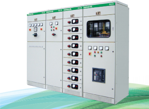
What is high voltage switchgear? It is the combination of circuit breakers, disconnectors, earthing switches, busbars, instrument transformers and protection relays, housed in cabinets or enclosures, that switches, isolates and protects circuits above 1 kV. In industry the term usually covers medium voltage gear from about 3.3 kV to 40.5 kV (for example 6, 10, 20 and 35 kV systems); in utility language “high voltage” often means transmission levels above 52 kV.
Every substation, large factory, mine, water works and power plant relies on it to receive incoming power, distribute it to transformers and large motors, and disconnect faults within milliseconds. This guide explains what is inside it, the main types, the ratings you need to specify, and where it is used.
Key takeaways
- It switches and protects circuits above 1 kV; most industrial installations are in the 3.3–40.5 kV medium voltage range.
- The core parts are the circuit breaker (usually vacuum), disconnector, earthing switch, busbars, CTs/VTs and protection relays.
- Main types: air-insulated (AIS), gas-insulated (GIS), metal-clad withdrawable cabinets and ring main units.
- Specify rated voltage, rated current, short-circuit current, internal arc classification and IP rating.
- IEC 62271-200 is the main international standard for metal-enclosed medium voltage switchgear.
What Is High Voltage Switchgear Used For?
- Switching – connects and disconnects feeders, transformers and motors under normal load.
- Protection – detects overcurrent, earth faults and other abnormal conditions through CTs and relays, then trips the breaker to clear the fault.
- Isolation – provides a visible or verified break and earthing so maintenance staff can work safely.
- Measurement – meters and transducers report current, voltage, power and energy to operators and SCADA.
Main Components
| Component | Function |
|---|---|
| Circuit breaker | Interrupts load and fault currents; vacuum breakers dominate up to 40.5 kV |
| Disconnector (isolator) | Provides safe isolation when the breaker is open; not designed to break load |
| Earthing switch | Connects the isolated circuit to earth before work starts |
| Busbars | Copper or aluminium bars that distribute power between panels |
| Current transformers (CTs) | Step current down for relays and meters |
| Voltage transformers (VTs/PTs) | Step voltage down for relays and meters |
| Protection relay | Measures CT/VT signals and trips the breaker on faults |
| Surge arresters | Limit overvoltages from lightning and switching |
Types of High Voltage Switchgear
By insulation
- Air-insulated switchgear (AIS) – uses air between live parts; lowest cost and easy to maintain, but needs the most space.
- Gas-insulated switchgear (GIS) – live parts sealed in gas; very compact and suited to cities, offshore platforms and high altitude.
- Solid-insulated / hybrid – conductors encapsulated in epoxy; compact and increasingly used as an SF6-free option.
By construction
- Metal-clad, withdrawable cabinets – such as KYN28-12, with each function in its own earthed compartment and a breaker on a withdrawable truck.
- Fixed-type cabinets – breaker or switch fixed in place; simpler and cheaper, but maintenance needs a longer outage.
- Ring main units (RMUs) – compact load-break or breaker units for secondary distribution rings.
For a detailed comparison of insulation technologies see AIS vs GIS vs vacuum switchgear.
A Typical Line-Up
Most industrial installations use a line-up of panels connected by a common busbar. A typical 10 kV substation in a factory might include:
- Incoming panel – receives the utility or generator supply, with a breaker, CTs, VTs and the main protection relay.
- Metering panel – houses voltage transformers and revenue or check metering.
- Bus coupler (if two incomers) – connects or separates two bus sections so one supply can feed both if the other fails.
- Transformer feeders – supply the 10/0.4 kV transformers that feed the low voltage switchboards.
- Motor feeders – supply large medium voltage motors, often with differential or thermal protection.
- Capacitor bank feeder – supplies power-factor correction equipment.
The arrangement is always shown on the single-line diagram, which is the key document for designing, quoting and operating the switchgear. Learn to read one in our single line diagram guide.
Ratings to Specify
| Rating | What it means |
|---|---|
| Rated voltage (Ur) | Highest system voltage the equipment is designed for, e.g. 12 kV or 40.5 kV |
| Rated normal current (Ir) | Continuous current the busbar or feeder can carry, e.g. 630 A, 1250 A, 3150 A |
| Rated short-time withstand current (Ik) | Fault current the equipment can carry for a set time, e.g. 25 kA for 3 s or 31.5 kA for 4 s |
| Rated peak withstand current | First peak of the fault current, typically 2.5 × Ik at 50 Hz |
| Internal arc classification (IAC) | Whether the enclosure protects people at the front, sides and rear during an internal arc |
| Degree of protection (IP code) | Protection against solid objects and water, e.g. IP4X for the enclosure |
Where It Is Used
- Incoming and distribution substations in factories, mines and process plants
- Power plants and renewable energy collector systems
- Water and wastewater treatment works with large pump motors
- Commercial buildings, hospitals, data centres and campuses supplied at medium voltage
Testing and Maintenance
Because faults at this voltage carry a lot of energy, testing before and after installation is essential:
- Routine factory tests – power-frequency voltage withstand, main circuit resistance, mechanical operation of breakers and interlocks, and checks of secondary wiring, carried out on every panel before shipment.
- Type tests – performed once on a design to prove its short-circuit, temperature-rise, dielectric and internal arc performance. Ask the supplier for the type test reports that cover your exact ratings.
- Site acceptance tests – insulation resistance, CT/VT polarity and ratio, relay secondary injection and functional trip tests before energising.
- Planned maintenance – typically every 3–5 years: cleaning, torque checks on busbar joints, breaker timing and contact resistance, relay testing and thermographic scans under load.
How to Choose a Supplier
- Confirm the design is type-tested to IEC 62271-200 for the voltage, current and short-circuit ratings you need.
- Check the internal arc classification and how arc gases are vented in your switch room.
- Ask for a complete drawing set, routine test reports and a spare parts list with every delivery.
- Make sure the protection relays and communication protocol match your site standard and SCADA.
- Choose a supplier who can support commissioning and after-sales service in your region.
Danli designs and builds high-voltage switchgear cabinets and KYN28-12 metal-clad switchgear for industrial and utility projects. Request a quote with your single-line diagram and ratings.
Frequently Asked Questions
Under IEC terminology 11 kV is medium voltage. Many industries still call it “high voltage” because it is far above the 400/230 V used by loads.
IEC 62271-200 covers AC metal-enclosed switchgear from above 1 kV up to 52 kV. Circuit breakers are covered by IEC 62271-100, and common requirements by IEC 62271-1.
Switchgear is designed for higher voltages and fault levels with compartmented construction and separate protection relays. A switchboard is a low voltage assembly for distributing power to feeders.
With planned maintenance, medium voltage switchgear typically lasts 25–30 years or more.